Guide
MCP diagram automation: 4 real-world use cases
Four real-world use cases for automating diagrams over MCP, from architecture that tracks infrastructure to SOPs drawn at a scale no one has time to draw by hand.
Diagrams have always been hard to create, harder to keep current, and disconnected from the systems they describe. Architecture diagrams go stale the moment infrastructure changes. SOPs sit in Confluence without visual summaries because no one has time to draw hundreds of them. Solution architects spend days piecing together context from scattered systems before they can put pen to paper. Coding agents ship code that ignores recommended patterns and prior approved solution architectures because they can’t see them.
The Model Context Protocol (MCP) changes this. MCP lets AI clients orchestrate across sources of truth – codebases, docs, infrastructure, tickets, transcripts – and put diagrams in the middle of those workflows instead of off to the side. A diagramming MCP server is what makes diagrams readable, writable, and connectable for the AI clients your team already uses (Claude, Cursor, Windsurf, ChatGPT). For a breakdown of which diagramming MCP servers stack up against each other, see Best diagramming MCPs in 2026.
This post walks through four use cases that demonstrate what becomes possible:
- Add diagrams to Confluence at scale
- Aggregate multiple contexts to build an as-is diagram
- Provide architecture context to coding agents
- Generate diagrams from customer discovery call transcripts
Use case 1: Add diagrams to Confluence at scale
The problem
Most Confluence wikis and SOPs are wall-to-wall text. For lab technicians at a biotech company, dense procedural pages are harder to consume, so steps get skimmed, missed, or performed out of order. In a regulated environment, those mistakes carry compliance risk and can compromise experimental results. Adding diagrams fixes this, but a typical Confluence space has hundreds of SOPs covering sample handling, instrument calibration, reagent prep, and cleanroom procedures. Manually summarizing each one, drawing a diagram, and embedding it back into the page is weeks of work no one on a lab ops or quality team has time for.
The workflow
- The user prompts their AI client to go through Confluence SOPs in a specific space and add one summary diagram per page.
- The AI client uses the Confluence MCP server to list pages, then fetches them one at a time.
- For each page, the AI client decides whether a diagram would help. If yes, it summarizes the SOP into a flowchart spec capturing each atomic step a technician must perform.
- Before generating the first diagram, the AI client uses the Eraser MCP to create a folder titled “Confluence diagrams” and a set of blank Eraser files, one per page, named after each Confluence page.
- For each file, the Eraser MCP generates a flowchart using the page summary plus a set of meta-instructions the user supplied (style, layout, naming conventions, decision-node highlighting) that apply uniformly across the batch.
- The Eraser MCP exports each diagram as an image and returns both the image and a shareable URL.
- The AI client uses the Confluence MCP to embed the image and the URL back into the original Confluence page.
The prompt
Go through every page under the “Lab SOPs” space in Confluence. For each page, decide whether a summary diagram would make the procedure easier for a technician to follow at the bench. If yes, generate a flowchart in Eraser that captures the atomic steps in a clear top-to-bottom sequence. Create a folder in Eraser called “Confluence diagrams” and save one diagram per page, named after the page title. Use our standard SOP style, put decision points and safety checks in orange, and highlight any compliance-critical steps. Once each diagram is generated, embed the image at the top of the source Confluence page along with a link to the editable Eraser file.
The outcome
Hundreds of SOPs get consistent, on-brand visual summaries in a single run. Lab technicians can scan a diagram at the bench instead of parsing paragraphs of procedural text, which reduces procedural deviations and supports audit readiness for FDA, ISO, or GxP compliance. The diagrams stay editable in Eraser, so when an SOP changes the diagram updates beside it instead of going stale and falling out of compliance with the written procedure.
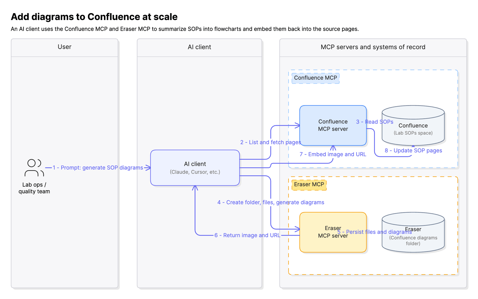 Confluence + Eraser MCP workflow
Use case 2: Aggregate multiple contexts to build an as-is diagram
The problem
A Fortune 500 company needs an as-is architecture diagram for a complex internal application. The context required to draw it accurately is scattered across four systems: Confluence holds the deployment guides, AWS holds the actually-running infrastructure (some of it deployed manually outside of IaC), a GitHub repo holds the Terraform that defines the rest, and ServiceNow CMDB holds configuration details and ownership metadata. A solution architect has to query each system, reconcile the inevitable drift between what’s documented and what’s actually running, and then draw a diagram by hand. The result is days of work spent on discovery before any real architectural analysis can begin.
The workflow
- The user prompts their AI client to build an as-is architecture diagram for a specific application by iteratively pulling context from multiple sources of truth.
- The AI client uses the Confluence MCP server to fetch the application’s deployment guides and runbooks.
- The AI client runs AWS CLI commands to enumerate the running footprint in the application’s AWS account, including resources that may have been deployed manually outside of Terraform.
- The AI client greps the local GitHub repo for Terraform files that define the application’s infrastructure-as-code footprint.
- The AI client hits the ServiceNow CMDB API to fetch configuration items, dependencies, and ownership for the application.
- As gaps and inconsistencies surface (a resource appears in AWS but not in Terraform, a service is referenced in Confluence but missing from the CMDB), the AI client iterates on steps 2 through 5 to fill them in.
- Once the context is reconciled, the AI client builds a structured prompt and passes it to the Eraser MCP server, including layout instructions and the team’s architecture style.
- The Eraser MCP generates the complex as-is diagram and returns the file and a shareable URL.
The prompt
Build an as-is architecture diagram for the “Claims Processing” application. Start by reading the deployment guides for this app in the “Platform Engineering” Confluence space. Then enumerate the running footprint in our AWS account 12345 across the us-east-1 and us-west-2 regions. Cross-reference what’s running against the Terraform in the platform-infra repo to identify manually-deployed resources. Pull the CI list, dependencies, and owners from the ServiceNow CMDB for the application service “claims-proc”. Reconcile any inconsistencies by going back to the source. When you have a complete picture, generate the diagram in Eraser using our standard architecture style, grouped by AWS account and region, with manually-deployed resources flagged in red. Save it to the “As-is architectures” folder.
The outcome
A complex as-is diagram that would have taken multiple days of manual context-gathering is produced in roughly thirty minutes. More importantly, the solution architect spends their time on the work that actually requires judgment, identifying single points of failure, cost optimization candidates, security gaps, and modernization opportunities, rather than burning the engagement on discovery. The diagram also stays connected to its sources: when the underlying infrastructure changes, the same workflow can be re-run to refresh the diagram instead of letting it go stale.
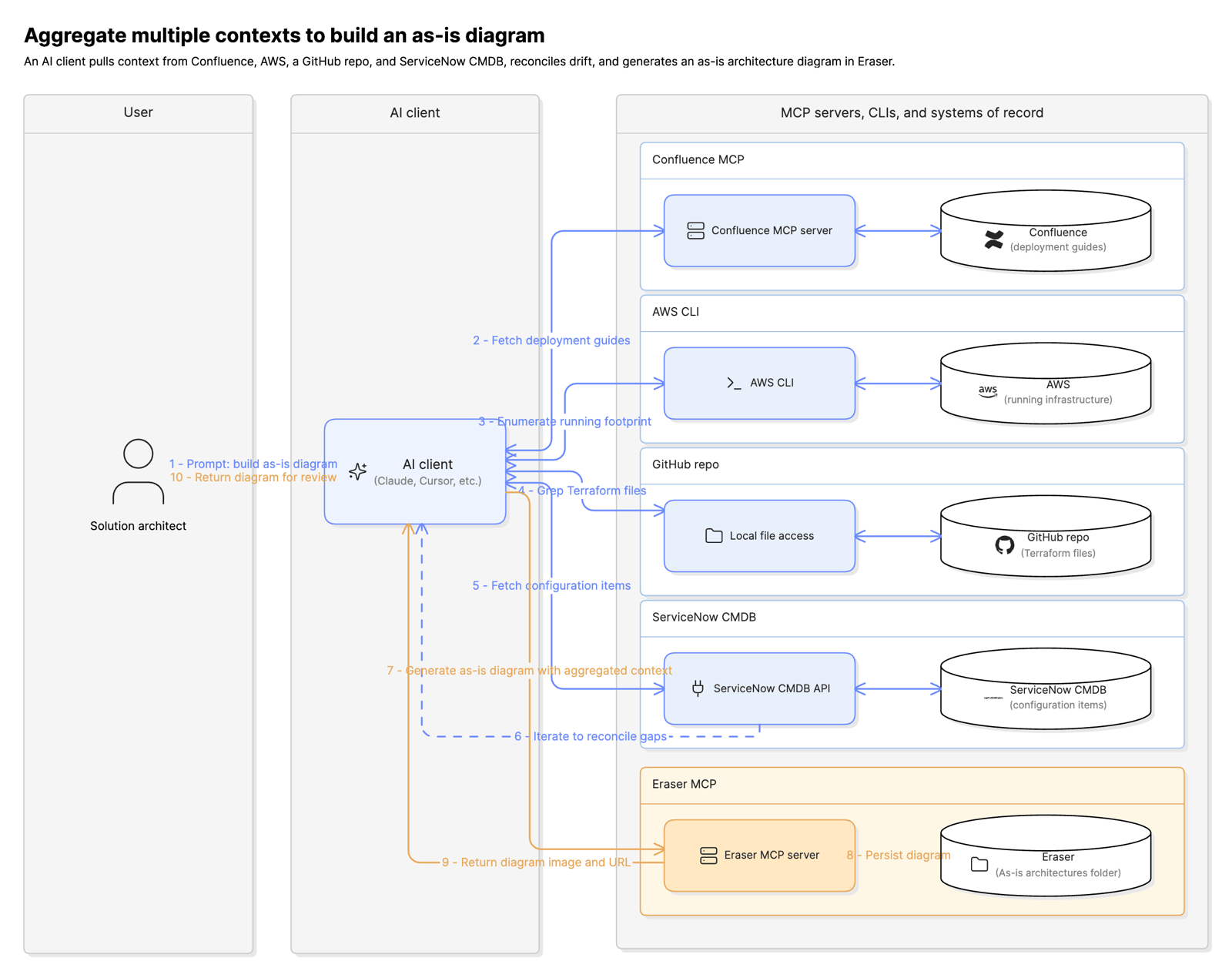 Confluence + AWS + GitHub + ServiceNow + Eraser MCP workflow
Use case 3: Provide architecture context to coding agents
The problem
Coding agents are excellent at writing functional greenfield code but poor at grounding that code in enterprise context and governance. The most useful context for that grounding lives in diagrams: existing infrastructure, reference architectures, approved patterns, and prior solution architectures from similar projects. Without access to these, the coding agent ships something that runs but fails architecture review, duplicates infrastructure that already exists, or violates patterns the organization has standardized on. The fix-up work after the fact often costs more than the original implementation.
The workflow
- A developer or solution architect prompts a coding agent (Claude Code, Cursor, Windsurf, Devin) to build a new feature or service.
- The coding agent enters planning mode. An Eraser skill is installed that instructs the agent to begin any non-trivial plan by querying Eraser for architectural context.
- The coding agent formulates search queries based on the request (the domain, the integrations involved, the data flows) and uses the Eraser MCP server’s search tool to find relevant diagrams: existing infrastructure, reference architectures, prior solution architectures for similar features, and approved patterns.
- The coding agent uses the Eraser MCP to read the most relevant diagrams in full.
- With that context loaded, the coding agent formulates an architecture for the new feature that reuses existing infrastructure where it can, follows the approved patterns, and aligns with prior solution architectures.
- The coding agent uses the Eraser MCP to create a new architecture diagram for the proposed implementation, applying the team’s standard style.
- The coding agent embeds the diagram in the plan document and returns the plan to the user for review.
The prompt
The user’s prompt to the coding agent is whatever feature request they would normally give it. The interesting prompt is the one the Eraser skill instructs the coding agent to run against the Eraser MCP before any code is written:
Before planning the implementation, search Eraser for context relevant to this feature. Run searches for: (a) existing infrastructure in the domain (e.g., “payment processing infrastructure”), (b) reference architectures and approved patterns for the relevant component types (e.g., “event-driven service reference architecture”), and (c) prior solution architectures for similar features (e.g., “subscription billing solution architecture”). Read the most relevant 3 to 5 diagrams in full. Use this context to formulate a plan that reuses existing infrastructure, follows approved patterns, and aligns with prior solution architectures. Then generate a new architecture diagram for the proposed implementation and include it in the plan document.
The outcome
The coding agent builds in a compliant, secure, scalable architecture that is far more likely to pass review on the first pass and rarely requires rework due to architectural issues. Engineering time is spent shipping the feature rather than redoing it. Over time, the new architecture diagrams the agent produces also become reference context for the next agent run, compounding the value of the diagram library with every project.
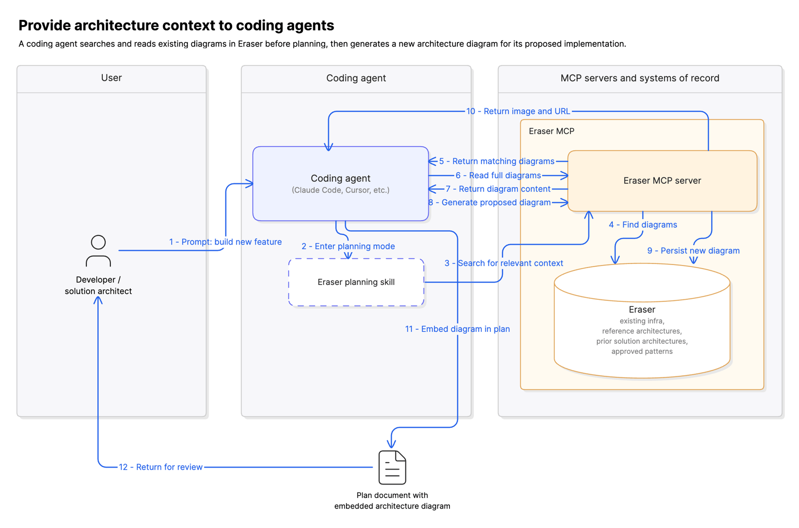 Coding agent + Eraser MCP planning workflow
Use case 4: Generate diagrams from customer discovery call transcripts
The problem
Solutions consultants run many discovery calls with prospective customers to gather context and requirements, usually following a structured format designed to extract a predictable set of inputs. After each call, the consultant has to produce a standard set of deliverables: an as-is architecture diagram of the customer’s current state, a to-be diagram of the proposed solution, and a follow-up proposal deck. Turnaround time is typically two to three days because the consultant has to re-listen to the call, summarize it, draw the diagrams, and assemble the deck. By the time it lands, the conversation has gone cold, momentum has dropped, and the deal has slowed.
The workflow
- A discovery call concludes on Microsoft Teams or Zoom, which triggers a follow-up agent.
- The agent uses the Teams or Zoom MCP server to fetch the call transcript and any recording metadata.
- The agent parses the transcript to extract the customer’s stated current-state architecture, pain points, and requirements for the to-be state.
- The agent sends two requests to the Eraser MCP server: one to generate an as-is diagram of the customer’s current architecture, one to generate a to-be diagram of the proposed solution. Both requests include the consulting team’s standard layout and styling instructions so the diagrams match the firm’s deliverable format.
- The Eraser MCP returns the two diagrams as image files and shareable URLs.
- The agent uses the PowerPoint MCP server to open the firm’s standard proposal template and place the two diagrams into their designated slides, along with a transcript-derived summary of the requirements and proposed approach.
- The agent emails the completed proposal deck to the customer (and the consultant) as the follow-up package.
The prompt
The trigger is automatic, so the interesting prompt is the one the agent sends to the Eraser MCP for each diagram:
Generate two architecture diagrams based on the attached discovery call transcript with [Customer Name]. The first is an as-is diagram of the customer’s current architecture: extract all systems, integrations, and data flows the customer described, including any pain points or bottlenecks they called out (flag these in red). The second is a to-be diagram of the proposed solution: incorporate the requirements and constraints they specified, and follow our standard solution architecture pattern for this use case. Use our firm’s standard styling: left-to-right flow, grouped by environment, with our standard component icons. Save both to the “Customer proposals / [Customer Name] / [Date]” folder and return image files and editable URLs.
The outcome
Diagrams are produced within five minutes of the call ending rather than two days later. The follow-up proposal lands in the customer’s inbox the same day, often while the call is still top of mind, which keeps the deal moving and the conversation warm. Consultants spend their time on the work that requires judgment (qualifying the deal, refining the solution, responding to customer feedback) rather than on diagram production. The downstream effect is faster sales cycles and higher win rates on deals where momentum matters.
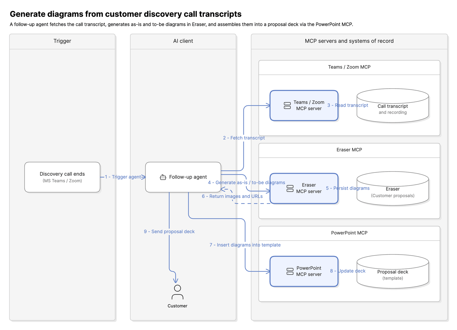 Teams/Zoom + Eraser + PowerPoint MCP workflow
Try it with Eraser
Across all four use cases the pattern is the same: an AI client orchestrates across multiple sources of truth, and a diagramming MCP server makes diagrams a first-class, connected node in that workflow rather than a disconnected artifact produced after the fact. The diagrams stop being deliverables and start being infrastructure.
To try these workflows yourself, start with the Eraser MCP setup docs to wire Eraser into the AI client your team already uses – or install in one click from the official Claude directory or ChatGPT plugin directory listings. For a deeper comparison of how Eraser’s MCP server stacks up against Lucidchart, Mermaid, Miro, and Excalidraw across CRUD depth, customization, layout control, inputs, and editing modes, see Best diagramming MCPs in 2026.