Guide
How to draw a hybrid cloud architecture diagram: VMware and AWS
Connect vCenter and an AWS account to Eraser, scan both, and ask one prompt for a diagram of the data center, the cloud and the link between them.
A hybrid cloud has two halves, and each half has its own console. vCenter knows the virtual machines and AWS knows the VPC. Neither draws the other, so the diagram that shows both is usually a slide someone drew by hand, out of date on both sides.
This guide draws one hybrid cloud architecture diagram from both. You connect VMware and AWS to Eraser as read-only data sources, scan them, and ask one prompt that reads both. Setup takes about twenty minutes. The link between the data center and the cloud needs the most care, and step 3 covers it.
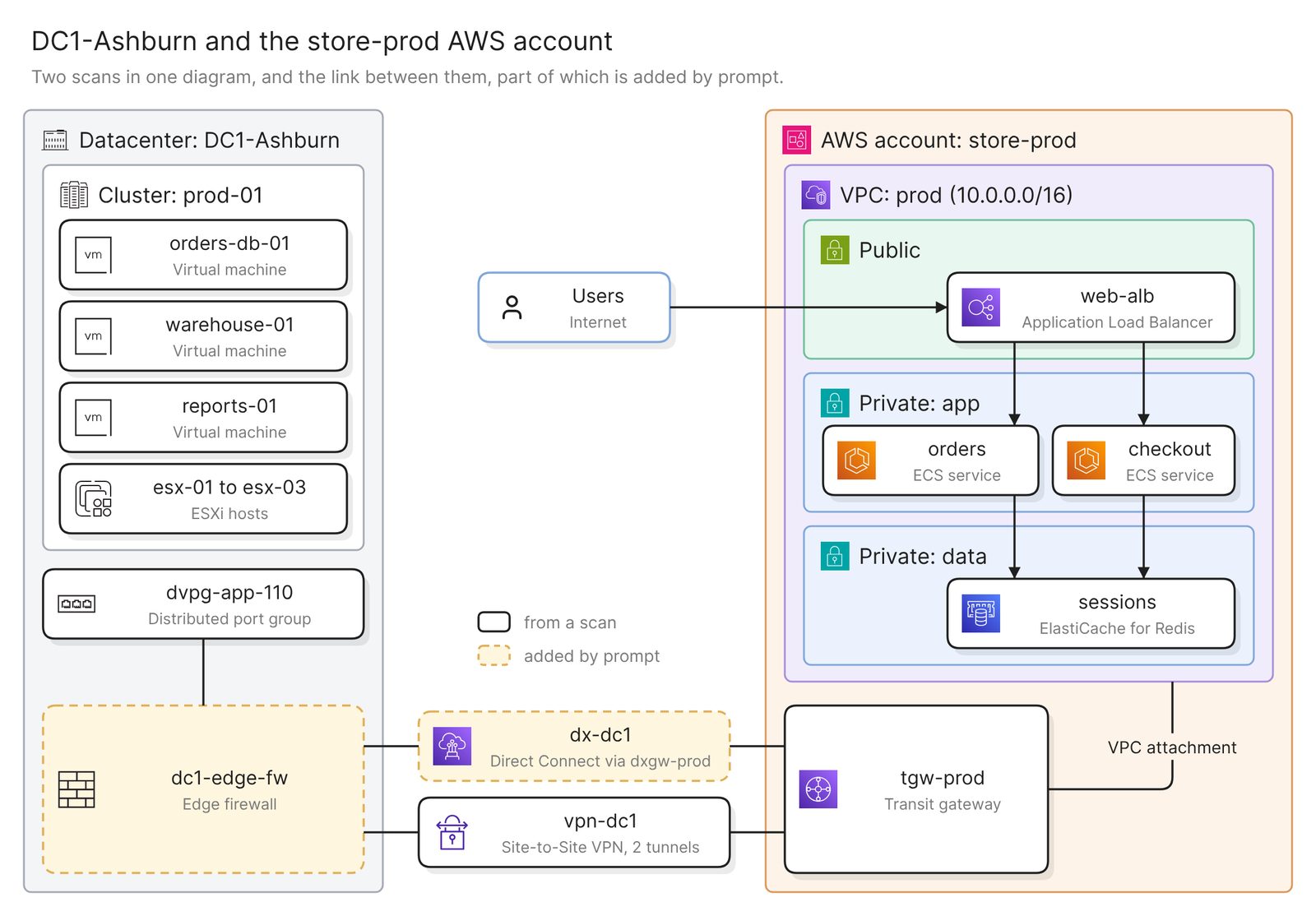 Example: a VMware data center and an AWS account, joined by Direct Connect and a backup VPN
Before you start
You need three things:
- Access to Eraser
- Access to vCenter, with permission to create a read-only account, or an inventory export such as an RVTools file
- Access to the AWS account, with permission to create a read-only role
The VMware scan holds virtual machines, hosts, clusters and datastores, and the AWS scan holds how the account is configured. Neither sees traffic or holds a record that joins the two sides, so the link and anything that crosses it need your input.
Step 1. Connect both sides
VMware connects in one of two ways. A live connection reads vCenter through an account that holds only vCenter’s built-in Read-only role, and vCenter has to be reachable from Eraser over HTTPS. If yours sits on a private network, upload an inventory export instead, such as the RVTools vInfo sheet. The VMware docs have the steps for both.
AWS connects with a CloudFormation template that creates one read-only role. The AWS docs have the steps, and the AWS guide covers that side in full.
Each connection scans when you set it up and builds a model, an inventory of what that side holds and how it connects.
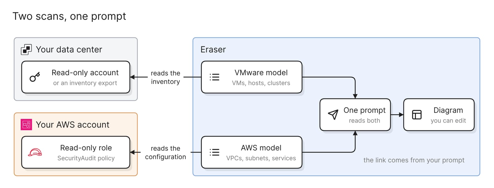 What the two connections set up
Other sources connect the same way. Cisco Meraki or Catalyst Center covers the on-premises switches and appliances, as the Cisco guide shows. Azure and Google Cloud take the place of AWS, or sit beside it in a multi-cloud estate.
Step 2. Ask one prompt that reads both models
Open AI chat and attach both models. One prompt can read up to five. Name each side the way its console names it:
Draw one architecture diagram of the DC1-Ashburn datacenter and the
store-prod AWS account. Put the data center on the left and AWS on the
right, as two top-level groups. Group virtual machines by cluster, and
AWS resources by VPC and subnet. Do not connect the two groups yet.
This asks for two inventories side by side, the vSphere hierarchy and the account’s VPCs and subnets. A model covers everything its connection imports, so name the datacenter and the account. For a large estate, narrow the VMware side to one cluster or folder. Hundreds of virtual machines in one group answer no question.
The last sentence matters. Neither model says how the two sides connect, so a link drawn at this stage would be a guess.
Step 3. Add the link, then check it
Each scan holds a different amount of the link.
- The AWS scan holds the cloud end of a VPN. VPN connections, transit gateways, their attachments and route tables are in the model. Do not count on customer gateways, virtual private gateways or Direct Connect resources being there. Open the model and look before you rely on them.
- The VMware scan holds none of it. It stops at the port groups the virtual machines use. The firewall or router at the data center edge is not a vSphere object.
So you describe the link yourself:
Add the link between the two groups. The data center edge is the firewall
dc1-edge-fw. It reaches the transit gateway tgw-prod two ways: the Direct
Connect connection dx-dc1 through the Direct Connect gateway dxgw-prod,
and the Site-to-Site VPN connection vpn-dc1 as a backup. Draw each path
once and label it with its name.
AWS’s definitions say what belongs on each path. A Site-to-Site VPN connection “offers two VPN tunnels between a virtual private gateway or transit gateway on the AWS side, and a customer gateway on the on-premises side”. The customer gateway is an AWS record that “represents the customer gateway device in your on-premises network”, so draw the device and its customer gateway as one box. Direct Connect “links your internal network to a Direct Connect location over a standard Ethernet fiber-optic cable”, and a Direct Connect gateway sits between its virtual interface and a transit gateway or virtual private gateway.
Check five things before you share it:
- Both sides are present. Compare the clusters with vCenter and the VPCs with the AWS console. Missing virtual machines usually mean an old or filtered export.
- The link is drawn once, and labeled. One named line joins the edge device to the AWS gateway for each path. The two tunnels are a label on the VPN.
- Each path ends on the right gateway. Compare the VPN connection’s ID, state and target gateway with the VPC console. Check Direct Connect in its own console, because no scan backs that part.
- Names match each console. Virtual machines appear as vCenter lists them, and AWS resources by name or ID. Anything you typed is only as right as your typing.
- Routes and ranges agree. The VPC route tables should send the data center’s range to the gateway. AWS recommends “non-overlapping CIDR blocks” when VPCs connect to an on-premises network.
Ask for the view you need
Each of these prompts asks for a different diagram of the same two scans.
How the data center reaches the cloud
Draw only the network path between DC1-Ashburn and the prod VPC: the
port groups, the edge firewall, both links, the transit gateway, and the
route tables and subnets that route to the data center. Leave out
virtual machines and services.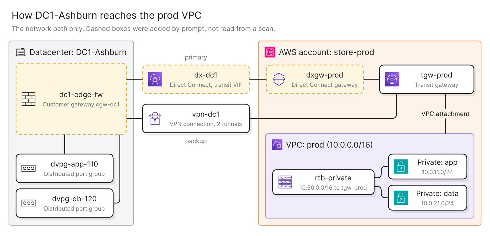 Example: the network path, with the parts added by prompt in dashed boxes
This is the diagram for a network review, and for documenting an AWS Direct Connect architecture. In a larger estate the transit gateway is the hub of a hub-and-spoke network.
One application across both sides
Diagram the online store across both sides: the load balancer and the
orders and checkout services in AWS, and the virtual machines
orders-db-01 and warehouse-01 in DC1-Ashburn. The orders service calls
orders-db-01 on port 5432 and warehouse-01 on port 443. Label every line
that crosses between the two sides.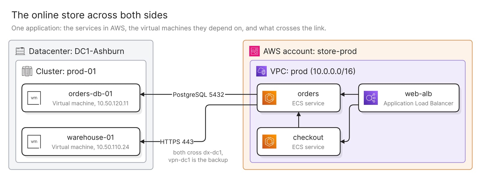 Example: one application, with the two calls that cross the link labeled
Neither scan records which service calls which virtual machine, so the prompt says it. If a CMDB records those dependencies, attach its model as well.
What has moved and what has not
Draw the migration state of the online store. On the left, its virtual
machines in DC1-Ashburn, with powered-off machines in gray. On the
right, the AWS resources that replaced them. Join each replaced machine
to its replacement with a dashed line: web-01 to web-alb, orders-app-01
to orders, checkout-app-01 to checkout.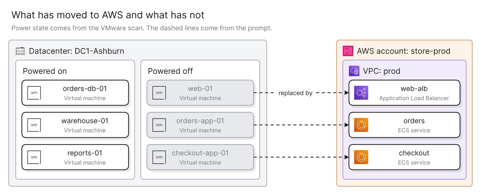 Example: three machines still running on VMware, and three replaced by AWS resources
Power state comes from the VMware scan. Which resource replaced which machine is in neither scan, so the prompt lists the pairs.
What disaster recovery depends on
Draw a disaster recovery view. DC1-Ashburn is the primary site and the
store-prod account is the recovery site. Show the production virtual
machines on the left and the AWS resources named after them on the
right, and flag every machine that has no counterpart.
Replication is in neither scan, so the match is by name. Treat a flagged machine as a question for its owner. The glossary covers what a disaster recovery plan needs beyond the diagram.
Keep it current
The diagram reflects the last scan of each side, and nothing scans on a schedule. After a change, rescan the side that changed, or upload a new export if VMware came in as a file, then regenerate. Verify checks an existing diagram against both models and lists every issue without changing it. It has nothing to check the typed parts against, so recheck the link by hand after a network change.
Share the finished diagram with a link, embed it in your team’s wiki, or export it, with Visio among the formats.
To take access away, remove both connections in Eraser, then delete the vCenter account and the CloudFormation stack.
Other ways to draw a hybrid cloud architecture diagram
- Use each vendor’s own view. The vSphere Client’s topology diagrams of a distributed switch “show the structure of virtual machine adapters, VMkernel adapters, and physical adapters in the switch”. As of November 2026, VCF Operations for networks draws a network map of physical and virtual devices, and its supported products table lists AWS as a data source the map does not cover. In AWS, the VPC console’s resource map shows one VPC’s subnets, route tables, and internet and NAT gateways, and AWS Global Networks for Transit Gateways shows registered transit gateways with their VPN and Direct Connect gateway attachments, where you add the on-premises sites and devices by hand. They are the right choice during an incident, and each one draws its own side.
- Draw it from the CMDB. If ServiceNow already records the virtual machines and the cloud resources, a map drawn from the CMDB follows one application across both, as the ServiceNow guide shows. It is the better choice when the question is about dependencies, and only as complete as the relationships people recorded.
- Draw it by hand with the vendors’ icons. AWS publishes its architecture icons as an icon package and PowerPoint toolkits, and draw.io lists AWS and VMware among its shape libraries. This suits a design that is not built yet, such as a planned Direct Connect link. Nothing checks the drawing against either side.
FAQ
Can one diagram show VMware and AWS together?
Yes. Attach both models to the same prompt, which can read up to five. You add the link between them by prompt.
Does the diagram show AWS Direct Connect?
Not reliably from the scan. The AWS scan holds VPN connections and transit gateways. Look in the model for your Direct Connect connection and gateway. If they are not there, name them in the prompt and check them in the Direct Connect console.
Does vCenter have to be reachable from the internet?
For a live connection, Eraser has to reach vCenter over HTTPS. If yours is only reachable on a private network, upload an inventory export instead, or ask your Eraser administrator about private connectivity.
Does the diagram update when either side changes?
Not on its own. Rescan the side that changed, then regenerate the diagram or run Verify on it.
Where to go next
To start from a description instead of a scan, the VMware diagram generator and the AWS diagram generator each draw one side from plain English, and the network diagram generator draws the link.
For reference diagrams, see a network diagram for disaster recovery, the Landing Zone Accelerator and a physical network security diagram. The glossary covers landing zones, high availability and cloud computing architecture.